Another DIY GPS logger approach

5 years ago
Reply
Register to post, see what you've read, and subscribe to topics.
decrepit
decrepit
WA
12872 posts
WA, 12872 posts
24 Feb 2026 7:35am
clearly SD card is either full or stuffed, and there is no list of past sessions to delete.
My SD card has also died, it's not logging sessions either, although it does say there's room left on the card.
ausbinny
ausbinny
200 posts
200 posts
25 Feb 2026 10:06am
Likely - I go through a bunch of SD cards @ my work for photography generally either camera won't detect the card or when ofloading image files will be corrupt files (weird looking / blank / static images)
TerryF
TerryF
WA
74 posts
WA, 74 posts
25 Feb 2026 3:19pm
Thanks for this next suggestion. I've booted both units and the SD card on the bad one looks to be the problem. Only 20kb local memory listed. Other unit has 29782mb SD memory listed. Problem Solved.

Now I just need to work out if it can be fixed. I think that the unit is 'factory' sealed by the maker and internals may also be sealed in epoxy. Stay tuned.


decrepit
decrepit
WA
12872 posts
WA, 12872 posts
25 Feb 2026 5:16pm
Just be careful, you don't cut into the battery, that could lead to fire!

Thought I might be able to point you in the direction of the card, but whoever made that has done something different. My card sticks up at top right of the display, there's no room for that to happen on yours.
TerryF
TerryF
WA
74 posts
WA, 74 posts
25 Feb 2026 7:02pm
Thanks for the warning Decrepit. I will be consulting with the maker of the unit when I see them next to see what can/needs to be done to sort out the SD card.
I haven't named them here, in case someone takes my comments as a complaint about their workmanship. A faulty SD card is just that, a part has failed, and that is not their fault (just my bad luck).
It would be great if it can be easily replaced but if not I hope some of the other components are salvageable
decrepit
decrepit
WA
12872 posts
WA, 12872 posts
25 Feb 2026 9:25pm
TerryF said..

It would be great if it can be easily replaced but if not I hope some of the other components are salvageable


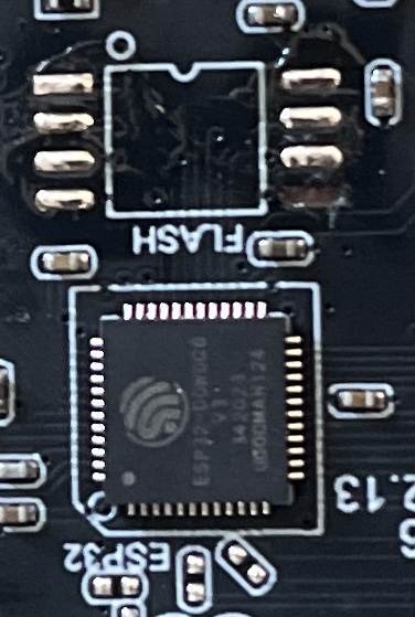
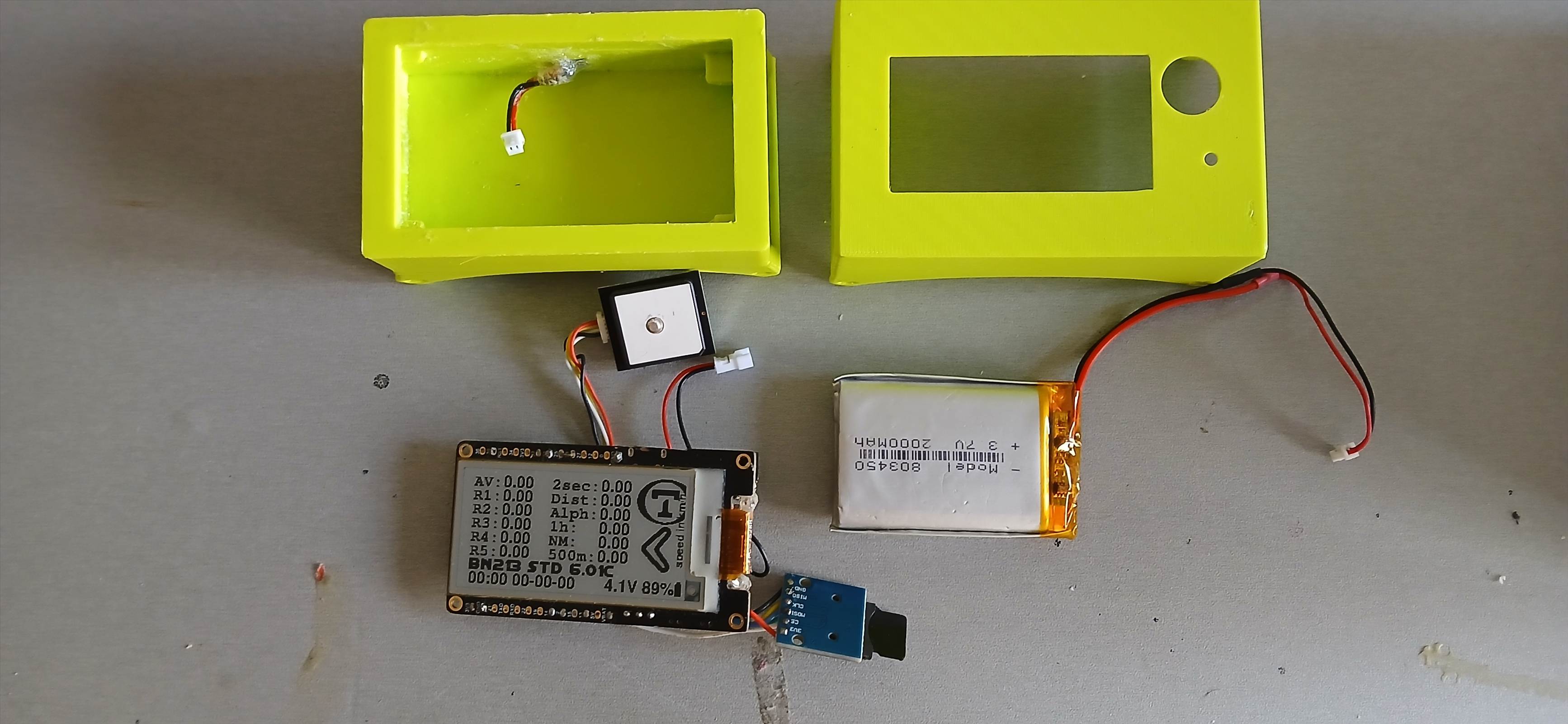
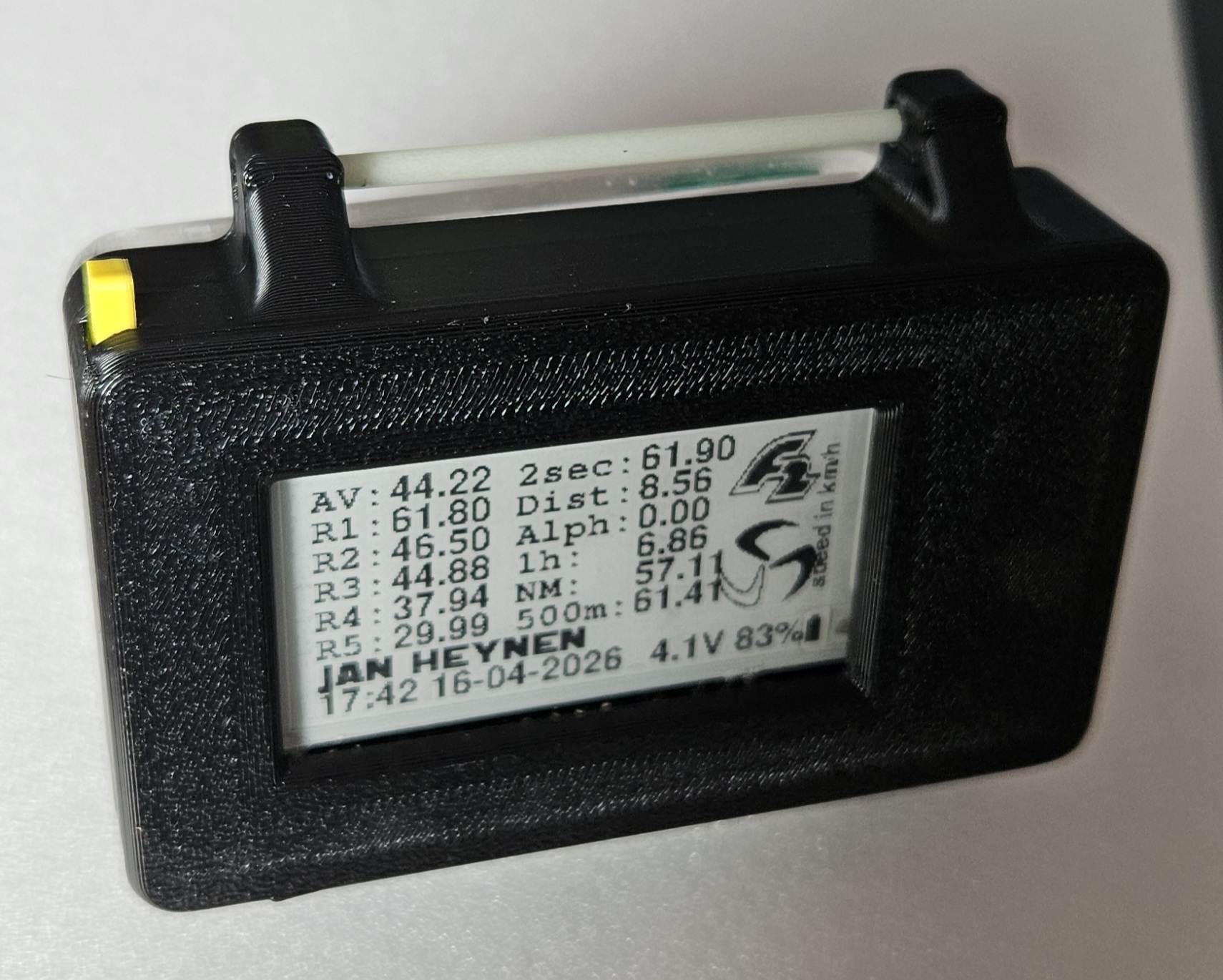
I managed to salvage the antenna, the RF charger and the board. The battery had failed, so didn't try that.
It's a matter of going very slowly with patience.

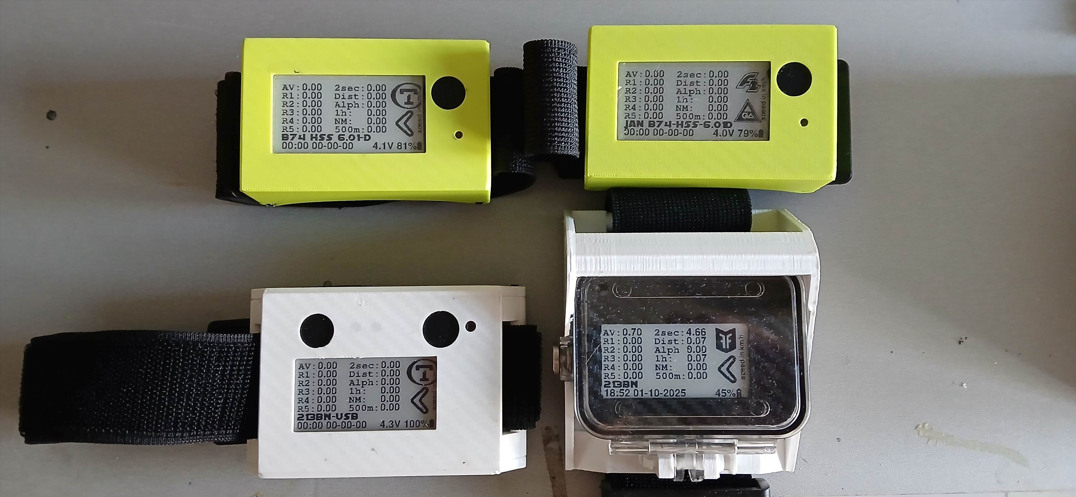
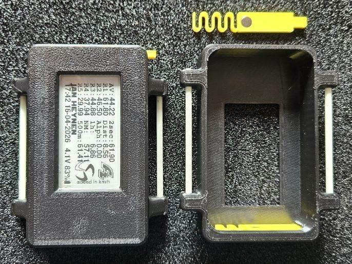
I built an arm unit with the bits, and carry it in a good waterproof armband.
Although the unit it self isn't water proof, there's a few advantages.---
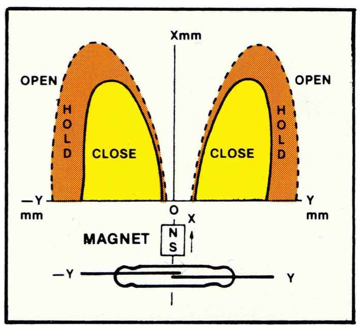
No messing about with magnets,
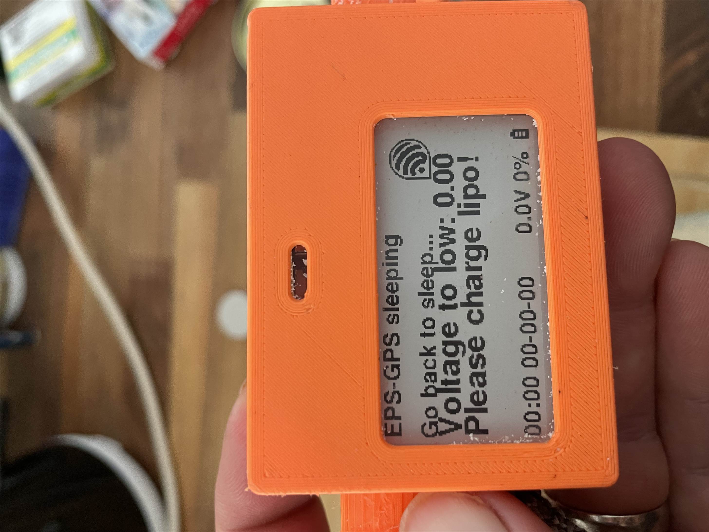
usb charging, much faster and doesn't overheat the device.
Everything is replaceable.
battery doesn't drain when not in use, so maybe top up charge in 6 months not fortnightly.

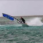
Main disadvantage, it's not as easy to see as a boom mount when sending it.
TerryF
TerryF
WA
74 posts
WA, 74 posts
26 Feb 2026 10:35am
Unfortunately, the epoxy encasement of the internals has caused parts to break in my attempt to salvage some of them. As I expected it would. At least I've been able to see how the unit was put together. Time to order another one


Actimel87
Actimel87
29 posts
29 posts
18 Mar 2026 9:09pm
Hallo,

I need some help, during desolder the flash to exchange it with an 16mB I defekt the ESP.

Does someone know were to jump wire the broken pin?


Actimel87
Actimel87
29 posts
29 posts
19 Mar 2026 2:30pm
Found it:)


it works with the 4MB partition, but how to update the partition_16MB.csv. Do I need to change the Rtos5.ino.partitions.bin?
rp6conrad
rp6conrad
376 posts
376 posts
19 Mar 2026 6:19pm
If you flash the ArduinoOTA Webupdater.ino, you have to copy the correct "partitions.csv" in the ArduinoOTA Webupdater folder. Then compile the sketch and flash it again. A 16 MB partitions.csv with spiffs can be found here : github.com/RP6conrad/T_display/blob/main/partitions.csv
This partition gives about 13 MB diskspace


Actimel87
Actimel87
29 posts
29 posts
19 Mar 2026 6:57pm
Thank you,

is it not possible to do with the ESP download tool?
I never had luck with Arduino update.
rp6conrad
rp6conrad
376 posts
376 posts
28 Mar 2026 8:02pm
The inductive charger with Lipo output 4.2V comes with a small ferrite tape. This is no good if your lipo is positioned near the receiver coil ! A bigger ferrite shielding solves the issue !

Greetings, Jan.
Flex2
Flex2
WA
373 posts
WA, 373 posts
28 Mar 2026 9:30pm
Such a huge difference! Nice one Jan!
PacoRaapNL
PacoRaapNL
148 posts
148 posts
29 Mar 2026 4:36am
Ready for the new 2026 season.
The 2 lime greens are the latest and final versions.No wireless charging.Pogo pins on the side to charge the battery.


rp6conrad
rp6conrad
376 posts
376 posts
2 Apr 2026 6:00pm
Next "How to" vid is online. A complete view on my process of soldering and assembling the ESP-GPS. Sealed housing made of PMMA, lasercut out of 15 mm GS PMMA and handcut top and bottom out of 2mm GS PMMA.
Greetings, Jan.
PacoRaapNL
PacoRaapNL
148 posts
148 posts
3 Apr 2026 1:21am
Nice detailed video Jan.
rp6conrad
rp6conrad
376 posts
376 posts
12 Apr 2026 4:05am
Another vid about the ESP-GPS. This time about 3D design in Onshape (PMMA parts and PETG Casing), and printing the case on my Bambulab P2S printer.
3D design is public : cad.onshape.com/documents/a511908aaa4bc53df3b62f8d/w/f84be4db970c8f87e32cc9d8/e/14282a33f523fa3330552c2c
Greetings, Jan.
veton
veton
47 posts
47 posts
21 Apr 2026 7:47pm
For those with charging coils, I'm about to try inserting a thermostate into the charging coil, in the base plate. My bases get very hot and if you are not aware can deform the plastic enclosure. Could be a solution so you can just place the gps on charge and forget about it.
Anybody has experience with this parts:
es.aliexpress.com/item/1005005689214002.html?isdl=y&aff_fsk=_okkENJu&src=RedbrainESGeneral&aff_platform=aff_feeds&aff_short_key=_okkENJu&pdp_npi=4%40dis%21EUR%210.42%210.21%21%21%21%21%21%40%2112000034016899151%21afff%21%21%21&dp=CjwKCAjwwJzPBhBREiwAJfHRnZoJkjFLEJfM3ucbjwXVDxdE8C58SA1Jva8qTJDxyvXE257PfuGVHxoCaF8QAvD_BwE
thanks
mathew
mathew
QLD
2167 posts
QLD, 2167 posts
23 Apr 2026 9:27am
@veton - do you mean to write "thermostat" ?

Yes - all wireless charging _requires_ a temperature sensor at or close-to the coil. If the case is melting it is clearly getting too hot, but that isn't the main reason...

... you do not want to cook the batteries. Ever. Unless you want some pyrotechnics.
rp6conrad
rp6conrad
376 posts
376 posts
27 Apr 2026 5:56pm
I integrate the magnet for the reed switch in the 3D housing. Seems to work perfect. There could be a corrosion issue in the long run for the neodumium magnet (6*3), but this can easily be replaced. The magnet is exactly in front of the reed switch, but the orientation N-S is in the direction that the reed switch will not trigger. Only if you move the magnet 3 mm out of the center, the reed switch will trigger.
3D designs are public in onshape :
cad.onshape.com/documents/1a133db3bc3e572121f2d2b0/w/41124def46406a956a0f502a/e/4113362641da97c18bf510e6?renderMode=0&uiState=69ef32a73b0ac217822dcfa0


veton
veton
47 posts
47 posts
27 Apr 2026 7:29pm
mathew said..
@veton - do you mean to write "thermostat" ?

Yes - all wireless charging _requires_ a temperature sensor at or close-to the coil. If the case is melting it is clearly getting too hot, but that isn't the main reason...

... you do not want to cook the batteries. Ever. Unless you want some pyrotechnics.


As far as I know none of the chargers had any thermostat. I'm making my own and thinking on including one to be able to put the devices on charge careless.
cheers
mathew
mathew
QLD
2167 posts
QLD, 2167 posts
28 Apr 2026 4:24pm
veton said..
As far as I know none of the chargers had any thermostat. I'm making my own and thinking on including one to be able to put the devices on charge careless.
cheers


It will depend on the brand, eg: the Texas Instruments BQ51050BRHLR has a "TS/CTRL" pin which you connect an NTC (negative temp coefficient) / thermistor.
Flex2
Flex2
WA
373 posts
WA, 373 posts
29 Apr 2026 10:36pm
rp6conrad said..
I integrate the magnet for the reed switch in the 3D housing. Seems to work perfect. There could be a corrosion issue in the long run for the neodumium magnet (6*3), but this can easily be replaced. The magnet is exactly in front of the reed switch, but the orientation N-S is in the direction that the reed switch will not trigger. Only if you move the magnet 3 mm out of the center, the reed switch will trigger.
3D designs are public in onshape :
cad.onshape.com/documents/1a133db3bc3e572121f2d2b0/w/41124def46406a956a0f502a/e/4113362641da97c18bf510e6?renderMode=0&uiState=69ef32a73b0ac217822dcfa0


Hi Jan, awesome idea. I'm no expert in Onshape but appears everyone can 'look' at your design but can't download the STL to print or modify. I'm sure your intention was to share freely. Possibly some setting you need to change?Separately, what are the white rods you are using for the strap holders? Fiberglass? I've been using carbon rods. Which is best?
rp6conrad
rp6conrad
376 posts
376 posts
30 Apr 2026 3:46am
Flex2 said..
Hi Jan, awesome idea. I'm no expert in Onshape but appears everyone can 'look' at your design but can't download the STL to print or modify. I'm sure your intention was to share freely. Possibly some setting you need to change?Separately, what are the white rods you are using for the strap holders? Fiberglass? I've been using carbon rods. Which is best?


White rods are fiberglass, was laying around here (from an old kite). I think that both (fiber or carbon) are stronger then the 3D PETG housing, so both types can be used.
The link to the 3D files on onshape do need that you have a (free) onshape account. I made some stl files and set these on github :
github.com/RP6conrad/ESP-GPS-Logger/tree/master/3D_housing
The breakout board for the SD nand is also on github :
github.com/RP6conrad/ESP-GPS-Logger/tree/master/SD_nand_128MB_breakout_EasyEda
But if you plan to make changes, certainly try out the onshape account : the 3D housing is with lots of parameters to change it to your own ideas.
I was today on the water with 4 ESP-GPS new design, worked perfect !
Greetings, Jan.
papae
papae
WA
12 posts
WA, 12 posts
3 May 2026 9:25pm
Hey, is anyone able to help me with my DIY GPS. I didn't build this so don't really know much about it. I left it too long without a charge and now it seems to be stuck in this low voltage loop.

I've tried putting it on the charger several times for different lengths of time but when you boot it up with the magnet it just goes straight to the low voltage.
is there a way to fix this or is it dead?

I'll try add a photo.


rp6conrad
rp6conrad
376 posts
376 posts
4 May 2026 3:52am
Try other chargers, your only chance is that the charge current is high enough so that the ESP can boot. The position on the charger is also important, the coil in the ESP should be aligned with the send coil. Try different positions. If you put it on the charger, it will try to boot, this is normal. When the it completes the boot, I will shut down again with the message voltage is low 2.8V. Just let it sit on the charger then for a couple of hours. When it is stuck in the bootloop, try another charger, and other positions.
Greetings, Jan.
Please Register, or first...
Topics Subscribe Reply

Return To Classic site 😭
Or... let us know if a problem, so we can tweak! 😅